When it comes to detecting light and movement with microcontrollers, one has quite a bit of options, after explaining each one, I will compare them for you at the bottom of this pots
LDR Light Dependent Resistor
This is the simplest one, and it only costs a few cents
Phototransistor
A photo transistor is in my oppinion a great tool to use with microcontrollers, very fast response time (Slightly slower than a photodiode), and can be used with the digital pins, the reason is that it works exactly like a transistor, but instead of enabling the current by providing voltage to the base, the current is provided from light !
So, if you were to connect the Emitter to ground, and the Collector to the digital pin, they would get connected when light is detected, that is it
Photo interrupter
A photo interrupter detects the presence, absence, or movement of an object by sensing when a light beam between an emitter and a receiver is blocked.
This is basically something you would find in your inkjet printer ! or in a factory (Conveyor belt), or most commonly, on en elevator (Door opens when an object is in the way)
The transmitter and receiver work together either side by side or opposing each other, when they are side to side, a mirror reflects the light onto the receiver
If you are trying to detect a red light or a light of the wavelength close to that of the interrupter, odds are that you can use the receiver on its own without the LED (Transmitter), simply do not power it up !
photodiode
PIR (Movement) sensors
PIR Sensors such as the HC-SR501 can detect movement, but they requier more than 1 component, the sensor itself, the plastic cover for the sensor (Pir Lens Cover creates a FRESNEL LENS), and an IC that amplifies the signal and analyzes it !
The cloud electric meter is a project consisting of a 3 parts
1- A microcontroller and a current transformer (As of now, I am using the SCT-013) 2- A server to collect the data from the microcontrollers 3- A mobile phone app to display the data
The second and third (Server and application) are beyond the scope of what we are doing here, here, I will be examining all the options for a microcontroller and current transformer, With and without the cloud part.
1- The no cloud setup
The first example we will be using is the current transformer (SCT-013) with a nodeMCU ESP8266 that shows data about the current on a screen, this is the simplest setup, and is for people who are here to figure out how to connect their transformer, To do this, you will need a 16 x 2 screen, and an LCD I2C Interface Adapter.
1- Connecting the LCD to an ESP8266 (Tutorials for arduino and ESP32 are all over the internet) 2- Connecting the Current Transformer 3- The software
Similar tutorials are all over the internet, this one is here so that I can have a compatible setup between all the devices in the IoT project, the way those 2 boards (The LCD and I2C board) are very popular, and are connected in more or less the same way in all tutorials, but since you are here, might as well make it as simple and complete as possible.
LCD displays require a lot of connected digital pins to work, but this is easily solved with a very cheap LCD-I2C board that connects to my 1602 (16×2) LCD display (Or 2004 20 x 4 LCD modules) with its 16 pins on one end, and connects to your microcontroller (ESP8266, ESP32, Or Arduino, etc…) via 2 I2C pins (SDA/SCL)
The LCD I2C Interface Adapter board is based of a popular 8-bit, remote I/O expander for the I2C bus namely the pcf8574T / ABX919… A remote expander can function as an LCD driver, but it also works for many other purposes, but that is beyond the scope of the simple instructions presented here, here we are interested in driving an LCD screen
The I2C address of can be set by setting the available solder points for addresses in the range of 0x20 – 0x27.
One thing you may want to know is that the jumper at one side of the nameless I2C board is for the LED backlight ! it can be fed through a separate power supply (Remember to combine the ground pins).
In this example, I am using an ESP8266 on a NodeMCU board.
Power
The ESP8266 and the ESP32 are 5V tolerant on the data pins (Proof here), So, because the linear voltage regulator on the ESP8266 NodeMCU board does not have a heatsink, we will be connecting the screen directly to the 5V power source, why burdain the small regulator with the screen !
So, on my I2C board, I connect the GND and VCC to the external power supply (Don’t power the board via USB and connect to the VIN, this is not how it works, VIN is for voltage input, not for output)
So, on my board, the geekcreit doit esp12f devkit v3 (In arduino studio, it is compatible with NodeMCU 1.0 – ESP-12E Module)
The data pins are connected as follows SDA – D2 – GPIO-04 SCL – D1 – SPIO-05
You are done with this, now, how to print to the screen !
the first step is to find the I2C address, my board provides addresses in the range of 0x20 – 0x27. without soldering anything, the address is probably 0x20, but if not, we can figure it out.
To figure out the address of your LCD display, use the following code
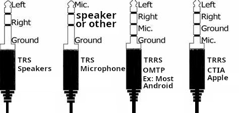
CTIA, which you can think of as apple, and i will call it apple throughout the post to help you focus on what matters, and OMTP, Which is everything else which i will call Android from here on.
For android (And almost any non apple device), the sleeve (Pin closest to the wire) is the ground, and the ring right above it would be the microphone… the other ring and the tip are the two speakers, right and left, In apple’s setup, the ground and microphone are switched together !
TRS
In a 3 pin connector (TRS), When it is meant to carry microphone signal, the tip is the microphone signal, the sleeve is still the ground, and the ring may carry any other signal such as a single speaker channel.
This special CAN BUS hardware (https://cantact.io/cantact/users-guide.html) is very nice in the sense that it lends itself to many possibilities, and this is why I am creating this separate post about it.
An alternative board is the https://canable.io/ board, but I will stick to the board I own for this post
The standard firmware for my Cantact is candlelight available at linklayer/candleLight_fw, And there is a firmware here (https://github.com/HubertD/candleLight), the official users manual page is here (https://cantact.io/) and here (https://github.com/linklayer/cantact-book)
Linklayer also provides some very nice tools such as (https://github.com/linklayer/cantact-app)
Now, with that out of the way, let us take a look at the board itself
microcontroller
etching reads…
stm32f
042CbTb
GH238 93
CHN 708
Which tells us that the microcontroller is an STM32, A great choice for such a device (See the wikipedia article linked)
On linux, can-utils is a great tool for this thing
I actually made a 3D model casing that fits the board perfectly, I will post it here when i find it
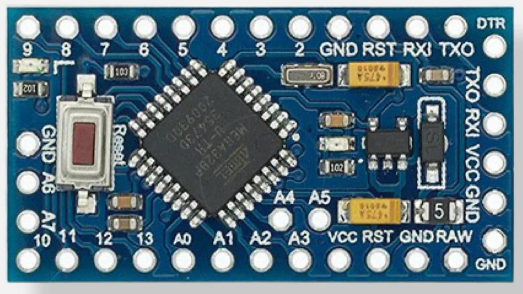
This arrangement comes in both, 3.3 and 5V, A4 and A5 are SDA and SCL, In case the voltage and clock speed are not silkscreened on the other side of the board, you can tell them apart using this method
This 3D printer was built back in 2015, I am adding this post here because I don’t remember much about it and i would need to rebuild it today for a certain project i have in mind.
My 3D printer, Prusa i3 with RAMPS 1.4 and a heated bed, started off with the config file from the FolgerTech i3-2020, the 0.4mm Brass Extruder Nozzle, 30mm M6 Tube, FILAMENT 1.75 mm
The entry that comes with the config files has a problem with DEFAULT_AXIS_STEPS_PER_UNIT, by default it comes with the values { 80, 80, 4000, 104.4 }, the third one (Z axis) has a problem that my rods are different, and the last one for the ext ruder has double the value assuming we have microsteps, So i reverted to the one in the 1.1.5 that is already installed, namely
The Z axis probably needs more refinement though, as the higher the build, the more problems you have close to the top
In this config file, I have the MOTHERBOARD set to BOARD_RAMPS_14_EFB instead of 33, this is all good for the 1.1.5 and the 2.0.x, previously they were numbers, and they probably still are (Value of this)
Even though i use a solid state relay for the extruder, the heated bed uses an automotive relay switch, so PWM is a big no no, we will need to comment the line where it reads define PIDTEMPBED, we also MIGHT WANT TO (only if needed) to fix some stuff in config advanced file.
if DISABLED(PIDTEMPBED)
 #define BED_CHECK_INTERVAL 5000 // ms between checks in bang-bang control
   #if ENABLED(BED_LIMIT_SWITCHING)
     #define BED_HYSTERESIS 2 // Only disable heating if T>target+BED_HYSTERESIS and enable heating if T>target-BED_HYSTERESIS
   #endif
 endif
the above means, check every 5 seconds, the rest is self explanatory in the code comments
Next, the end-stops, Z_PROBE_OFFSET_FROM_EXTRUDER for example (Height) is the most important one, as the others will simply print in the wrong location on the bed which besides loosing bed space is not really a problem
Could not find this setting in Marlin 2.0, pending further investigation
Now, the bed size, the whole bed is 20CMs, but there are screws at the edges, so I will go with 19 and add some 0.5 offset
Remember to uncomment “PROBE_MANUALLY” since i don’t have a probe ATM, also uncomment LCD_BED_LEVELING and leave RESTORE_LEVELING_AFTER_G28 uncommented (and leave ENABLE_LEVELING_AFTER_G28 commented the way it is)
This is a very old question, ever since Espressif removed the 5V tolerant statement from their datasheet no one felt safe connecting 5V directly to the digital input pins, but the news is out now, according to the CEO of Espressif himself, their boards are indeed 5V tolerant ON THE DIGITAL INPUT PINS
What pins are 5V tolerant exactly?
The IO pins in input state (sink) are 5V tolerant, Yet the power supply to the chip must be 3.3V (Most boards come with a regulator for this so it should not be a problem). other models do not come with a regulator, and in such a case, you will need to add the regulator, but even then you do not need a level shifter for the digital inputs. for the ESP32, The ones without an onboard regulator usually go for as little as $2.5 (5 boards for $12) , while the ones that come with a voltage regulator and a serial to USB adapter will set you back around $4.6 (3 for $14)
When pins on the Espressif microcontroller are set as output, they will use 3.3V logic, whether or not the difference in voltage between high and low will register on the other microcontroller/device is an issue related to the other microcontroller, from my experience, Arduino Uno works just fine.
Also note that analogue pins are a different story, the ADC pins use the power provided to the chip as a reference voltage. so a voltage divider is still required.
so in short, if you connect the 5V supply to the VIN pin (going through the onboard regulator), and use 5V logic on the digital pins while they are in input mode (Sink) you should good, and this is not just me, this is an official statement.
You may be wondering why is it not the in datasheet then ? The answer is, it used to be in the datasheet, but the company faced problems with people powering the chip itself with 5V so they omitted it to avoid confusion,
This is excellent news for someone like me who has to go through the hassle of logic level converters whenever coupling Arduino with ESP chips.
Before the CEO of the company made those statements, many people did their own experiments and found those results, but there were still doubts as to whether the results were conclusive or whether there was more to the story, a convincing experiment by ba0sh1.com did demonstrate that it was indeed 5 Volt tolerant on the input pins,
Where did i get this from
Swee-Ann Teo, who after my research seems to be from Espressif made the following statements
On whether ESP8266 is 5V tolerant, he had this to say on a facebook post by hackaday
“i can reply officially here: it is 5V tolerant at the IO. while the supply voltage is at 3.3V.”
On whether ESP32 and ESP8285 are also 5V tolerant
“ESP32 and ESP8285 are both 5V tolerant as well. but for ESP32, it is a very complicated matter. it supports 1.8V operations too… i don’t know where to start…”
When asked why this information is not in the datasheet, he responded
“the reason is too many users took it to mean that the chip is 5 V tolerant. When we say 5 V tolerant, we are only referring to the IOs. So some users mistook this to make that they can power the chip entirely off the 5 V supply. The correct usage is to use 5 V open for these 5 V tolerant pins, and only via only drain configuration.” And then elaborated on the matter with “I understand, but the time needed to do the iterations when mistakes were made, was too long. when the product was launched 5 V WiFi modules (with DCDC) were the norm. Many users saw “5 V” written in the specs and thought it could be a 1-1 replacement for such modules.”
One user asked if the tolerance towards 1.8 volts of the ESP32 was relevant to enabling battery operation, the response was no, specifically, Teo responded with
“actually not. but many memory devices are moving towards 1.8V operations, and we would be compatible with them as well.”
The facebook post where this is all written is here.
Even though this looks like a long post, I have composed it for a friend and unlike mostly everything else on this blog, this is not just for my own reference, so it should be easy to follow and understand (I hope).
What for ?
This is a very valid question, Why would i use a slower Arduino and connect it to WiFi using an ESP8266 you ask, why not just use the ESP8266 or even ESP32 as both the WIFI and the microcontroller to run our code? There are many situations where you would want to, the most common of which is the analogue and digital pins on an Arduino board, the friend I am writing this tutorial for is looking to use the 50 digital pins on an Arduino Mega Pro Embed as select lines for 50 Arduino pro mini boards, another might be the analogue pins on an Arduino (8 or 16 depending on the board), so digital and ADC pins on an Arduino might be needed.
You might ask why not an ESP32, it has a bunch of digital and analogue pins, the answer is that sometimes they are not enough, especially when you find out that the analogue pins on the ESP32 are divided into 2 groups, one of them is not usable if you enable WiFi.
Another valid reason is all the shields that have Arduino libraries but those libraries do not function with ESP, which is probably even more common of a problem than the pins problem.
So in short, even though the need might not arise very often, it does exist.
The ESP8266 as an Arduino WIFI shield
Arduino does not come with WiFi, there are shields from Arduino that provide WiFi, and those shields are based on ESP8266 which is a very cheap WiFi enabled microcontroller. but there is nothing stopping you from using any ESP8266 board and connecting it to your Arduino,
Which one: They should all work, and you probably already have one since you are here, I am personally using the slightly more expensive $4.6 boards that come with a USB-TTL chip and power regulator built in, if you want to use the cheaper boards (esp8266-01), you might want to connect it to the 3.3V output of your Arduino, but you will still need a level shifter, I would expect you also have a UART USB to serial board.
Price: models from the 01 ($2.5 each when you get 5 boards for $12 ) up to the 12E or 12F ($4.6 each when you buy them as 3 for $14). not bad for a WiFi enabled microcontroller !
Communication between Arduino and ESP8266
Arduino can talk to the shield either via UART or via SPI (Given the libraries written for this), SPI is up to three times faster than UART, but most of the time your application, be it sensor data or the like, will not be able to flood any of those 2 buses, In this post, I will cover both, SPI first then serial.
The components (hardware)
1- ESP8266 (Any variant should do) 2- Logic level shifter, since Arduino is 5V and ESPs are 3.3, I have been told that the ESP 12E and 12F are 5 volt logic tolerant, but I would think going with a logic shifter might save me something down the road, hours of debugging, or a new board, or something i fail to foresee 3- An Arduino, I am using a mega, but an UNO should do just fine (I will cover it) 4- Wires to connect all the above, and probably a breadboard (I like to solder things to a universal PCB board, but not everyone likes to do this) 5- A power supply, in my case a couple of micro USB cables and a 5V source that is my a power supply.
Software on the ESP8266
1:SPI: If you are going with SPI, you will need to flash JiriBilek / WiFiSpiESP onto your ESP8266, fortunately, this comes with an ino file that you can use your Arduino software to flash directly
2:UART-Serial: If you are going with serial, you might want to go with jeelabs / esp-link, mind you, Arduino themselves forked this before for their own WiFi shields, but since then, the jeelabs esp-link has added many features, so i would recommend you go with the original jeelabs.
Software on Arduino
1:SPI: if you have installed the SPI software from above on your ESP8266, the accompanying Arduino software would be JiriBilek / WiFiSpi, The library implements almost the same functions as the Arduino WiFi library.
2:UART-Serial: there is no library to go with this case that is beyond your regular serial bus if you want to exchange serial info, so if this is a 3D printer, software on your PC should be able to translate the data into serial, and it would be transparent, but what if you want to use WiFi from within Arduino, like a client that downloads pages or sends post data to pages,
Choice of UART-Serial vs SPI
UART-SERIAL, has certain advantages and disadvantages, with serial, i can simply update the software on the Arduino over the air over WiFi, I can get serial messages and use WiFi at the same time both as client and server, SPI on the other hand is faster, but it is not out of the box compatible with serial messages. Another disadvantage of SPI is that it needs a bit of extra code to allow the board to boot
Implementing WIFI over SPI
SPI – The hardware, how to connect
The H.SPI (On the ESP8266) is connected to the SPI on the Arduino like you would connect any SPI bus, with the addition of a logic level shifter (Red part in the photo), We connect Clock to clock, Slave select to select line, MOSI to MOSI and MISO to MISO, there is nothing to it. I have added a table for the Uno (Same for Arduino Pro Mini) and the Mega for your convenience
Now assuming you are done with the connection above, it is time to load some software.
SPI: Installing the WiFiSpiESP on the ESP8266
First, we need to load the software to ESP8266, the JiriBilek / WiFiSpiESP comes with a .ino file, so all you need to do is load that into Arduino studio, connect your esp8266, compile and upload, now this part is done, no modifications are needed to this code since all the control is passed on to the Arduino, compile and upload.
If you are having trouble uploading the code or selecting the board, my 12E board works in Arduino studio as NODEMCU V1.0, if you don’t have any ESP8266 boards in your boards list, you will need to add it, there are many tutorials on using Arduino with esp8266.
SPI: software on the Arduino
On the Arduino side, you will have to include the library (WiFiESP), then include it in your code, the library should be readily available in your libraries menu of your Arduino Studio.
NOTE: Both the library and the software you installed on your ESP need to have the same release number (0.2.5 at the time of writing) or it would not work, the software is hard coded not to work if they don’t match, you will be presented with the error (Protocol version mismatch. Please upgrade the firmware) in your serial console during runtime, I know this because a couple of weeks ago, I contacted the author (Jiri) through GitHub, and he brought both versions of the software and the library current so that they would match, it was a small thing but if you ever get this error in the future, you know where to go, he was quick to fix it within hours.
Now to the Arduino code, inside the library, there are examples, all you need to do is upload one of those examples, most likely, you would want to start off with the WiFiWebClient, this example that comes with the library needs to be modified in two locations, the first is the credentials to your WiFi, and the other is to change the server you are connecting to from www.example.com to wherever that web server is. this should get you started on most projects.
In my case, I have had to modify a few things in the script to make it work, first of all, a short delay needs to be inserted before we check if the WiFi is connected, the other is to not have it die but rather try again if it is not for a set number of times
WiFi using UART-Serial
UART-SERIAL should be the as easy, I should be back here
The ESP8266 has a TX and RX pin that should be connected in reverse to the ones on the Arduino, RX (Receive) should be connected to send, and send to receive, both boards need to share a common ground (reference voltage), and an Arduino mega should be able to provide 3.3 volts with sufficient current for the ESP8266 if you plan to power the ESP from the MEGA, if you have an ESP8266 with an onboard voltage regulator, you can simply add it to the power supply directly through the VIN pin (rather than the 3.3V pin)
You can run the whole board on 5V (AT YOUR OWN RISK), but that has to be done at the VCC pin (With an external regulated power supply) not the RAW pin, it will still run on an 8Mhz clock (The resonator is 8MHZ, you can’t change that without changing the resonator), and you will lose the voltage regulator (Since it is 3.3v) and use an external one.
Why can’t i, i hear you cry, the answer is simple, the CPU’s reference voltage is 0-3.3V when running on the built in regulator or 3.3V, if you step the voltage up on VCC to 5V regulated, and disconnect RAW altogether, and don’t care about the lower speed, then there you have it, it should work.
If any of my 3.3V Arduino boards gets fried this way, I will let you know, but for now this works for me.
We use cookies to ensure that we give you the best experience on our website. If you continue to use this site we will assume that you are happy with it.